
XYNC SDR Quadro
Beschreibung
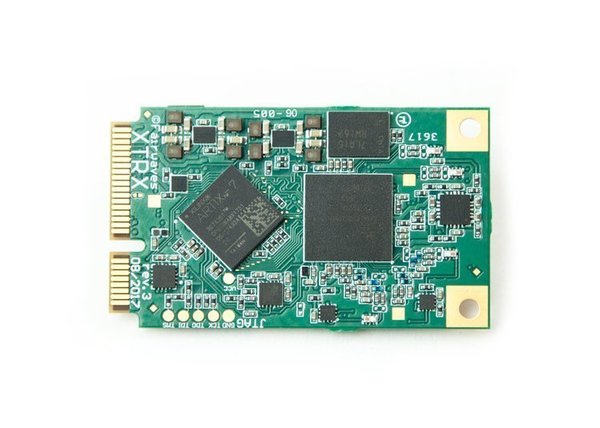
XYNC-SDR is a XTRX SDR-Modul Rack. HackRF One is an open source USB hardware platform. For Developer, Hacker and Pentester.
XYNC Quadro SDR PCIe Rack
The ultimate low-cost massive MIMO SDR, with up to 32x32 transmit/receive channels
Up to 16 XTRX Boards, Synchronized & Multiplexed
If you’re working on a massive MIMO system or have a large swath of spectrum you need to monitor, XYNC (pronounced iks-sync) is right for you.
You can connect two XYNC boards, either to increase the number of RX/TX channels (e.g., two XYNC Octos give you 32 TX and 32 RX channels) or to increase throughput per channel (e.g., two XYNC Quadros give you twice the throughput of a single XYNC Octo). Connecting more than two XYNC boards is also possible, but requires an external clock and 1 pps signal distribution circuitry, neither of which is provided as part of this campaign products.
Synchronized and Multiplexed XTRXs
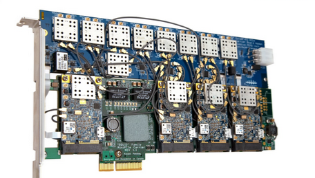
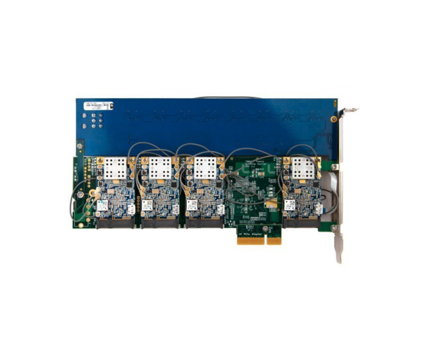
A single XYNC comes equipped with four or eight removable XTRX boards, metal installation brackets, cables for all of the TX/RX ports and the GPS port, and a special board for synchronizing the XTRX units. Each onboard XTRX provides two transmit channels and two receive channels. Thus, XYNC Quadro (with four XTRX units) has eight transmit and eight receive channels, and XYNC Octo (with eight XTRX units) has 16 transmit and 16 receive channels. Two XYNC Octo can be synchronized and will give you 32 transmit and 32 receive channels.
On the digital side, each XTRX unit is connected to a PCIe switch that multiplexes the XTRX PCIe lanes into a single PCIe 2.0 x4 connector. This makes it very compact and easy to install into a standard PC. Just don’t forget to provide enough air flow for cooling, as setups like this can get quite hot.
Features & Specifications
RF Chipset: 4x or 8x Lime Microsystems LMS7002M FPRF (double that for Tandem models)
FPGA: 4x or 8x Xilinx Artix 7 50T (double that for Tandem models)
Channels: 8×8/16×16/32×32 MIMO
Sample Rate: ~0.2 MSPS to 120 MSPS per channel (subject to the limitations explained above)
PCIe Throughput: PCIe x4 Gen 2.0, 16 Gb/s (double that for Tandem models)
RF Output Power: 0 to 10 dBm depending on frequency
RF Bandwidth: 1.4 MHz to 130 MHz (1.4 MHz to 30 MHz for the 6 GHz RX option)
Tuning Range: 30 MHz - 3.8 GHz
RX/TX Range:
10 MHz - 3.7 GHz
100 kHz - 3.8 GHz with signal level degradation
Reference Clock:
Stability w/o GPS: 100 ppb from 0°C to 70°C
Stability w/GPS: <10 ppb stability after GPS/GNSS lock
Form Factor: full-size PCIe
Bus Latency: <10 µs, stable over time
Synchronization: synchronize two XYNC boards directly or more than two XYNC boards with an external clock distribution network
RF Bandwidth
XYNC is based on multiple synchronized XTRX SDRs, so the maximum achievable RF bandwidth is a function of the individual XTRX RF bandwidths.
If you want to tune XYNC channels to receive or transmit at different parts of the spectrum, please keep two things in mind:
XTRX RF filters are not ideal and have natural roll-off towards the edge, so you might need to overlap the XTRXs' receive/transmit windows to achieve a contiguous spectrum within which to receive or transmit.
Each XTRX has only one receive and one transmit PLL, so both RX channels are "locked" to one other, as are both TX channels. This means that a single XYNC board only provides up to eight independent RX channels and eight independent TX channels. An XYNC Octo Tandem, for example, would provide 16 independent RX channels and 16 independent TX channels. Accordingly, it makes sense to run each XTRX in SISO mode.
XYNC Tandem
If you need greater throughput or more channels than a single XYNC can provide, consider a Tandem. As mentioned above, a Tandem is essentially two XYNC boards, connected by a cable and synchronized. Below are the primary reasons to choose an XYNC Tandem:
For the same number of channels, an XYNC Quadro Tandem has twice the per-channel throughput of a regular XYNC Octo. If you need 16 TX and 16 RX channels but the PCIe 2.0 x4 throughput of a single XYNC Octo is insufficient for your application, then an XYNC Quadro Tandem might be a better fit.
XYNC Octo Tandem has twice as many channels as XYNC Octo. So, if you need 32 TX and 32 RX channels for a higher order MIMO system, you'll need an XYNC Octo Tandem, even if the throughput of the XYNC Octo is not a limitation.
The 6 GHz RX flavour of XYNC is only available as a Quadro, with 8 TX and 8 RX channels, so XYNC Quadro Tandem is the only way to get 16 TX and 16 RX channels at 6 GHz.
Sampling Rate & Throughput Limits
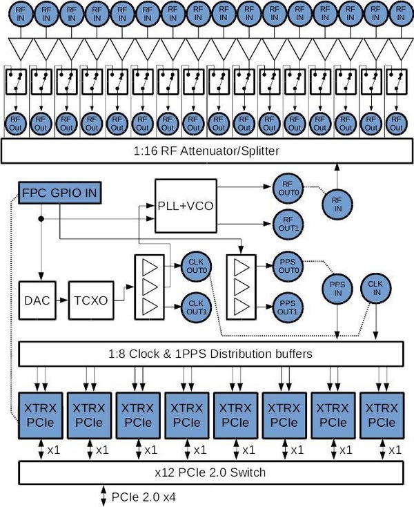
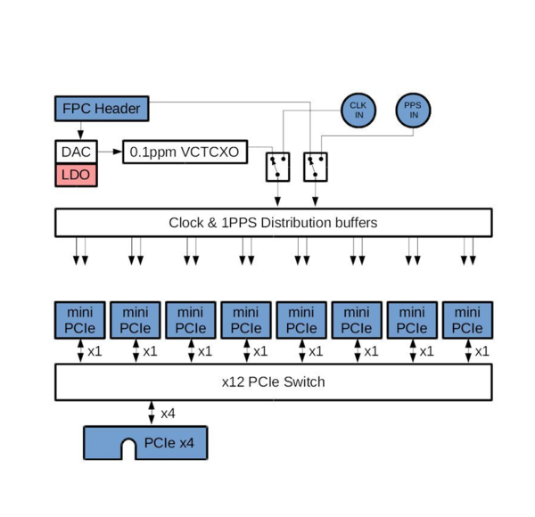
XYNC uses a PCIe switch to connect all of its XTRXs to a single PCIe bus. The XTRXs are connected to the PCIe switch with PCIe 2.0 x1 buses, and the switch is connected to the host with a PCIe 2.0 x4 bus, which introduces additional limits to the XYNC sampling rate and throughput compared to a single XTRX.
Expanding on the (theoretical) maximum XTRX throughput limits, we get the following throughput per channel for XYNC Quadro and Octo in various configurations. Green cells indicate combinations of sample rate and PCIe bus configuration where the sampling rate is not limited by the PCIe bus but by the XTRX itself.
SISO & MIMO configurations
In the table above, SISO configurations mean that only one receive and one transmit channel is used on each XTRX, i.e. XYNC Quadro would have 4x4 RX/TX channels and XYNC Octo would have 8x8 RX/TX channels. MIMO configurations mean that both receive and both transmit channels are used on each XTRX, i.e. XYNC Quadro would have 8x8 RX/TX channels and XYNC Octo would have 16x16 RX/TX channels. This is why SISO configurations enjoy twice the bandwidth per channel of MIMO configurations – they have half as many channels between which to share that bandwidth.
Synchronization & Phase Coherency
What exactly does XYNC synchronize? The answer is a bit complex. Below are some important facts you should keep in mind:
Each XTRX on an XYNC is a 2x2 MIMO transceiver and could be seen as a "channel pair." This means that each XTRX (i.e., each channel pair) can (but need not) be tuned to a different RF frequency. However, both channels in a given pair will always have the same RF frequency. Also, the RX and TX frequencies of each XTRX are tuned independently of other XTRXs.
The ADCs and DACs of all of the XTRXs on an XYNC are locked to a common reference clock. This means they are sampling with exactly same frequency but might sample at different points in time. In other words, any two XTRXs on an XYNC have a phase difference between them.
All XTRXs are locked to a common 1 pps synchronization signal, so timestamps are also synchronized between all sample streams.
Up- and down-converter PLLs are locked to a common reference clock but not phase-synchronized between XTRXs.
If you're looking to do direction finding or beamforming, you would need to take the extra step of calibrating the phases between all XTRXs. You can use either the built-in sine generator or an external sync sequence (e.g., from an external XTRX). Depending on your phase coherency precision requirements, you may need to repeat the calibration regularly (e.g., every half hour). See this update for an example of the phase stability measurements.
If you're looking for a non-beamforming MIMO, XYNC should work just fine as is.
Note that the XYNC software package does not currently include the phase calibration algorithm. Please contact us directly if you need support with phase calibration.
Power Consumption
XYNC consists of three main units:
The PCIe switch unit
The synchronization & frontend unit (classical or 6 GHz RX)
Several XTRX SDR units (4x for Quadro or 8x for Octo)
The power consumption of the PCIe switch and frontend units is relatively constant at about 10 W for the classical version.
XTRX power consumption varies significantly depending on whether you’re doing RX, TX, or both; on whether you’re doing continuous or burst TX/RX; and on output power, internal gains, bandwidth, digital pre-processing, and a few other parameters.
Cooling
With tens of watts of power consumption, cooling is important. Output power and other parameters of the LMS7002M chips we’re using begin to degrade at about 80°C. It’s important to keep the ambient temperature significantly below that to provide enough of a temperature gradient for the chips to cool. If you’re interested in phase stability, it’s also important to keep the temperature as stable as possible – temperature changes can noticeably affect phase stability, causing phase differences between the XYNC channels to drift.
For general applications, we recommend at least providing a stable flow of air through the PCIe compartment. For industrial applications, an external box with a passive heatsink might be a good choice. You can connect such a box to the PCIe bus with a PCIe bus extender.